
2026 Best Vacuum Brazing Process Guide for Buyers?

In 2026, buyers need more than a low quote when comparing vacuum brazing suppliers. The Vacuum Brazing Process can join complex metal parts with clean, precise joints, but results depend on materials, part design, and controlled production conditions. A joint that looks sound may still fail inspection if the assembly, filler metal, or temperature profile is poorly matched.

That sounds simple. It isn’t.

This guide explains the choices buyers should examine before requesting a quotation. These include base metals, joint clearance, furnace capacity, temperature uniformity, atmosphere control, and inspection methods. Ask how the supplier handles sample runs, process records, and dimensional checks. For example, a small gap between components can affect filler flow, while an uneven heating cycle may distort a thin assembly. Those details deserve attention before production begins.

No single supplier or process setting suits every component. Some trade-offs are easy to miss. A lower price may reflect different inspection coverage or a narrower service scope, so compare like with like. This guide offers practical questions for reviewing capabilities and estimating project fit, not a substitute for engineering validation. Share drawings, material specifications, and performance requirements with qualified specialists, then confirm the proposed process through suitable testing. A careful review can reduce surprises. It cannot remove every risk.
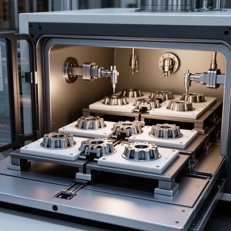
2026 Best Vacuum Brazing Process Guide for Buyers?

What Vacuum Brazing Is and How the Process Works

Vacuum brazing joins metal components by melting a filler metal while keeping the base materials solid. The parts are cleaned, fitted together, and placed in a sealed furnace. Air is removed to reduce oxidation during heating. Surface preparation still matters; vacuum cannot compensate for oil or heavy contamination.

As the furnace reaches the filler metal’s working temperature, the filler melts and flows into the narrow joint by capillary action. The base metals do not melt. That matters. After a controlled hold, the furnace cools the assembly, often under vacuum. The result can be a neat joint with little distortion, especially for complex assemblies that are difficult to weld.

Reliable results depend on more than furnace temperature. Joint clearance, filler selection, material compatibility, and part cleanliness all affect flow and strength. A gap that is too wide may leave an incomplete joint; one that is too tight can restrict filler movement. Not every alloy fits. Parts also need support so they do not shift during heating. Process trials and inspection help confirm the recipe before production. A trial may reveal an awkward detail: a joint that looks simple on a drawing can behave differently once heated.

Which Materials and Joint Designs Suit Vacuum Brazing

Vacuum brazing suits clean, closely fitted parts made from stainless steel, carbon steel, copper alloys, and many nickel alloys. These materials can form sound capillary joints when the filler metal wets both surfaces and the furnace cycle matches the base metals. Aluminum is also brazed in vacuum, but its tenacious oxide makes magnesium control and careful process development important. ASM Handbook, Volume 6A, describes how filler selection, surface condition, and temperature affect joint formation. Titanium and ceramic assemblies need extra scrutiny; ceramics usually require metallization or a suitable intermediate layer. Fit matters.

Joint design should give molten filler a short, continuous path. The AWS Brazing Handbook gives commonly used clearance guidance around 0.001–0.005 inch, with the best value depending on filler, materials, and brazing temperature. Its design guidance also uses an overlap length near three times the thinner member’s thickness as a practical starting point. Lap joints often provide more bonding area than simple butt joints, while sharp corners and blind pockets can trap gas or interrupt filler flow. A narrow gap is not automatically a better gap. Real assemblies may distort during heating, so measure clearance at brazing temperature where possible. That detail is easy to miss. Validate the design with representative coupons, since furnace loading and surface preparation can change results.

2026 Best Vacuum Brazing Process Guide for Buyers? - Which Materials and Joint Designs Suit Vacuum Brazing
Base Materials Common Filler-Metal Family Typical Brazing Range Suitable Joint Designs Buyer and Process Considerations
Stainless steel to stainless steel Nickel-based brazing alloys; silver-based fillers may suit lower-temperature service About 950–1,200°C for many nickel-based fillers; silver-based fillers commonly braze at lower temperatures, depending on composition Lap, sleeve, and scarf joints; butt joints generally need added support or a designed filler reservoir Choose the filler for service temperature, corrosion environment, and base-metal compatibility. Control joint clearance at brazing temperature; excessive gaps can reduce capillary filling.
Nickel alloys to nickel alloys Nickel-based brazing alloys Commonly about 1,000–1,200°C, subject to alloy solidus and liquidus Lap, nested, and scarf joints with continuous capillary paths Check whether the base alloy is precipitation-hardened and whether the brazing cycle will alter its properties. Specify post-braze heat treatment when required.
Aluminum alloys to aluminum alloys Aluminum-silicon brazing alloys Typically about 580–610°C for vacuum-brazing cycles, depending on alloy and filler Lap, channel, and plate-to-core joints; designs should allow filler flow and venting Oxide removal is critical. Magnesium is often used in vacuum aluminum brazing to assist oxide disruption; alloy selection and cycle control are essential to avoid base-metal melting.
Copper to copper Silver-based or copper-based fillers, selected for the required service conditions Silver-based fillers often braze at roughly 600–900°C; copper-based fillers require temperatures near or above copper’s melting point and need careful assessment Lap, sleeve, and tube-in-socket joints Consider the base metal’s melting point, electrical and thermal requirements, and the effect of the filler on conductivity. Avoid a cycle that risks melting or distorting the copper parts.
Cemented carbide to steel Silver-based or copper-based fillers, often selected to accommodate thermal-expansion differences Often about 700–1,000°C, depending on filler composition and component requirements Lap or supported insert joints with a thin, uniform bond line Carbide and steel expand differently. Joint geometry and filler selection should reduce residual stress; use a qualified cycle to limit cracking and distortion.
Titanium to titanium Titanium-compatible active or titanium-based brazing fillers Often about 850–1,000°C, depending on filler and alloy Lap and scarf joints with controlled, accessible clearances Titanium is highly reactive at elevated temperature. Use a suitable high-vacuum process and verify filler compatibility, contamination limits, and resulting joint properties.
Dissimilar metals, such as stainless steel to copper Silver-based or other compatible fillers chosen for both base metals Varies widely; commonly about 600–1,000°C depending on filler Lap, sleeve, and scarf joints are generally easier to design for capillary flow than unsupported butt joints Assess differences in melting point, thermal expansion, and metallurgical compatibility. A filler that wets one side may not wet the other; qualify the complete material pair.
General design guidance: Vacuum brazing is best suited to clean, tightly controlled assemblies with joints that provide continuous capillary flow. A room-temperature clearance around 0.025–0.10 mm is a useful preliminary range for many designs, not a universal specification; the appropriate clearance depends on the filler, materials, geometry, and temperature. Confirm the final joint gap and brazing cycle through filler-metal data and process qualification.

How to Prepare Parts and Select Brazing Alloys

Preparing parts well is as important as choosing the brazing alloy. Start with clean, dry components free from oil, marker ink, and machining residue. A thin film can disrupt wetting inside the vacuum furnace. Remove burrs, then check mating surfaces for flatness and consistent joint clearance. Measure several points; one tight corner can restrict alloy flow. Avoid touching cleaned areas with bare hands.

Choose an alloy that suits both base metals and the assembly’s service conditions. Compare its melting range with the metals’ solidus temperatures, then check expected operating temperature, corrosion exposure, and strength needs. Use the alloy supplier’s technical data and the furnace operator’s process limits. A sound choice on paper may still perform poorly if the joint gap or heating cycle is wrong. Test coupons can reveal that early.

Tips: Keep parts dry and handle them with clean gloves. Use small, measured filler preforms, and secure components with fixtures that tolerate the heating cycle. Record alloy lot, joint clearance, and furnace cycle for each trial. It is easy to focus too much on alloy selection; preparation errors are often harder to spot, and I would not treat one successful sample as proof of a stable process.

What Happens During Each Stage of the Vacuum Brazing Cycle

Vacuum brazing begins well before the chamber door closes. Technicians clean mating surfaces, remove oils, and place a measured filler-metal preform at the joint. Even a faint fingerprint can leave residue that disrupts wetting. Parts are loaded with room for thermal expansion and a clear path for gas evacuation. That sounds routine. Details matter.

The chamber is sealed, then pumps lower pressure while sensors track the vacuum level. Heating ramps bring the assembly toward the selected brazing range; the exact profile depends on alloy, mass, and joint design. At the soak, filler melts and flows by capillary action into the narrow gap. Too little heat can leave an incomplete joint; too much can erode edges or distort thin sections. Cooling follows a controlled profile, allowing the filler to solidify before the load is removed. After unloading, operators inspect the joint and review cycle records for temperature uniformity, pressure changes, and deviations. Small leaks or poor fit-up can still spoil a neat-looking part.

How Buyers Can Evaluate Quality, Cost, and Supplier Capability

A vacuum brazing quote should be judged by repeatability, not furnace temperature alone. Ask for recent load charts, temperature-uniformity survey results, vacuum records, and inspection data from comparable parts. Check whether thermocouples were placed near the actual components, not only at convenient chamber locations. Small details matter. A clean-looking assembly can still contain incomplete joints.

The ISO Survey 2022 reported more than 1.2 million ISO 9001 certificates worldwide. That figure shows how common quality-system certification is; it does not prove a supplier can braze your alloy, joint design, or production volume consistently. Certificates are not proof. Review the supplier’s documented process controls and corrective-action records. For thermal processing, ask how furnace calibration and temperature uniformity are managed against applicable requirements, such as AMS2750H. Request evidence, not just a procedure title.

Compare total cost per accepted part, including tooling, cleaning, inspection, rejected loads, and lead time. Ask for recent yield and rework figures, with the reporting period clearly stated. Then discuss capacity: available furnace size, load frequency, and contingency plans during maintenance. A low quote can hide costly delays. The uncomfortable part is that buyers may not receive comparable data from every supplier. Note the gaps, request clarification, and avoid treating an attractive price as proof of capability.

Back To Top