
Why Choose a Threaded Linear Shaft for Your Application?

A Threaded Linear Shaft can support both straight-line movement and secure component positioning within one compact assembly. Its threads allow nuts, brackets, or other fitted parts to travel along the shaft, while the shaft itself provides a defined path for motion. This combination can simplify equipment layouts where space is limited. It may also reduce the need for separate mounting and adjustment components. In a packaging machine, for example, a threaded shaft can help position a guide rail or adjustable stop. Small details matter. Thread pitch, shaft diameter, material, and surface finish all affect performance.

The design is not automatically right for every application. Loads, travel distance, speed, alignment, and operating environment should be checked before specifying a shaft. A fine pitch may offer more precise adjustment, while a coarser thread can move a component farther with each turn. But actual performance depends on the full mechanism, not the shaft alone. Lubrication, bearing support, and contamination can change wear and movement over time. A practical selection process compares these factors with the machine’s duty cycle and maintenance needs. When tolerances are tight, confirm dimensions with the supplier and test the assembly under realistic conditions. That extra check can feel tedious. It can also reveal a mismatch before installation, when correction is simpler and less costly.

Why Choose a Threaded Linear Shaft for Your Application?

What Is a Threaded Linear Shaft?

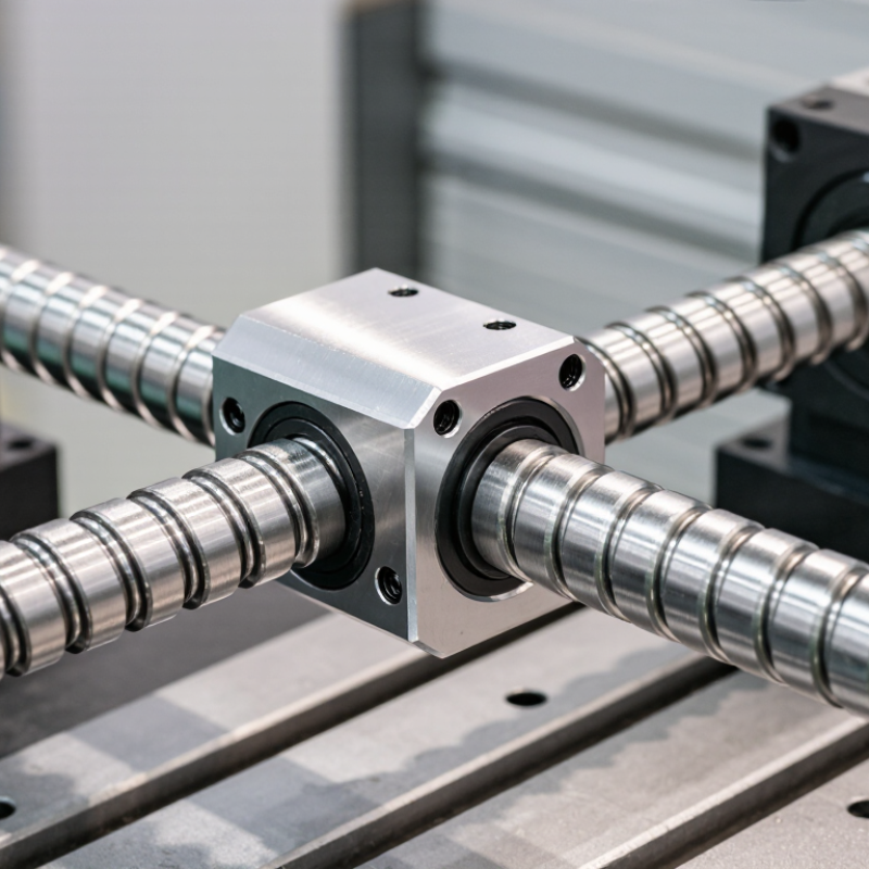
A threaded linear shaft is a round mechanical shaft with a helical thread along part or all of its length. A matching nut engages that thread, converting relative rotation into straight-line movement. Depending on the design, the shaft or nut may rotate while the other travels.

The thread’s lead—the distance the nut advances in one revolution—helps determine travel speed and positioning resolution. Pitch describes the spacing between adjacent thread peaks. They are related, but not interchangeable.

Picture a compact actuator moving a sensor carriage along a frame. The threaded shaft provides the drive, while separate supports and guides help control alignment and resist side loads. It is not a magic fix. Dust, poor lubrication, or a bent shaft can increase friction and cause uneven motion. Select a shaft by checking load, travel, speed, duty cycle, and available space; then confirm that the nut, bearings, and supports suit those conditions.

The International Federation of Robotics’ World Robotics 2024 report recorded 541,302 industrial robot installations worldwide in 2023. That figure reflects broad automation activity, not threaded-shaft use specifically, but it shows why dependable linear movement matters in equipment design.

A detail worth reconsidering: designers sometimes size the drive for load alone and overlook alignment.

How Threads Convert Rotation into Controlled Linear Motion

Why Choose a Threaded Linear Shaft for Your Application?

How Threads Convert Rotation into Controlled Linear Motion

A threaded linear shaft turns rotary input into predictable travel along an axis. As a nut follows the helical thread, each revolution advances it by a distance set by the thread lead. This makes motion measurable. A fine lead offers smaller movement per turn, while a larger lead moves farther with each rotation. The right choice depends on speed, force, and positioning needs.

In a compact fixture, a handwheel can rotate the shaft while a guided carriage moves a sensor toward a workpiece. The guide prevents the carriage from turning with the shaft; the threads provide the push. That distinction matters. Without proper alignment, side loads can increase friction and wear. For heavier loads or frequent cycling, check shaft support, thread engagement, lubrication, and expected duty cycle. Use measured loads, not guesses.

A threaded shaft can be practical when motion must be controlled without a complex drive system. It can also be slower or less efficient than other mechanisms, especially when friction is high. That tradeoff is easy to overlook. Before specifying one, compare the required travel per turn with motor speed, available torque, and acceptable backlash. A prototype often reveals small issues drawings miss, such as a carriage binding near the end of travel. Not glamorous, but useful.

Key Advantages in Positioning, Load Handling, and Design

A threaded linear shaft can combine guidance and motion in a compact assembly. Its thread converts rotation into controlled travel, making it useful for adjustment stages, fixtures, and positioning mechanisms. Choose the thread pitch around the movement you need: a finer pitch offers smaller increments, while a coarser pitch can move farther per turn. Check the actual positioning tolerance under working conditions; thread geometry, wear, and coupling flexibility can all affect repeatability.

Load handling depends on more than the shaft’s stated capacity. Consider axial force, unsupported length, speed, and how securely the shaft is mounted. A long shaft under compression may buckle, while poor alignment can increase friction and wear. Keep radial loads on suitable supports or guides rather than assuming the threaded section will handle them. Small details matter. A practical design review should include the nut, bearings, lubrication, and the structure around the shaft—not just the shaft itself.

Design flexibility is another advantage. Shaft length, end features, and thread specifications can be selected to fit a constrained layout, reducing extra adapters. Still, customization is not automatically better. It may complicate replacement or maintenance later. Measure available space, expected duty cycle, and service access before settling on a configuration. A prototype run under realistic load can reveal binding or backlash that a drawing may not show.

How to Select a Shaft for Travel, Load, and Operating Conditions

A threaded linear shaft should be selected around the motion it must deliver, not just its nominal diameter. Measure the full stroke, then add space for the nut, end supports, and deceleration. For a long horizontal span, shaft deflection can matter more than static strength. A small sag may cause binding or uneven wear. Check the manufacturer-neutral engineering inputs: unsupported length, support arrangement, speed, acceleration, and expected cycle count.

Load is not only the weight on the carriage. Include the moving mass, tool forces, shock, and any offset that creates a bending moment. ISO 281 sets a useful bearing-life reference: its basic rating life corresponds to 90% reliability under defined conditions, not a guarantee for every installation. Operating conditions count. Dust, moisture, temperature, lubrication, and frequent reversals can all change service life. A clean-room estimate may be too optimistic for a machine beside a cutting process.

For travel accuracy, compare lead, backlash, and required positioning tolerance with the process itself. A coarse lead may move quickly, but can reduce resolution; a fine lead can demand more torque. Verify critical dimensions against the applicable fit and tolerance specification, and test the assembly across its full stroke. Real motion can reveal what a spreadsheet misses. Keep a margin, but document why it is needed.

Where Threaded Linear Shafts Fit—and When Alternatives May Be Better

Why Choose a Threaded Linear Shaft for Your Application?

Where Threaded Linear Shafts Fit—and When Alternatives May Be Better

A threaded linear shaft can combine mounting, adjustment, and motion in one compact part. It may suit light-to-m moderate-load equipment, fixtures, and small positioning systems. When a compatible nut engages the thread, rotation can produce controlled linear travel. Performance depends on thread pitch, alignment, lubrication, and load; the shaft alone does not guarantee accuracy. A detail that is easy to overlook: side loads can increase wear and cause binding.

Tips: Check the load, travel distance, speed, and duty cycle before choosing a thread. Leave room for a nut, coupling, and maintenance access. A quick fit check can prevent a costly redesign.

A threaded shaft may be a poor choice when a smooth, low-friction guide surface is needed. For that job, a smooth shaft with linear bearings can be simpler. Long, fast travel may favor a belt drive, while a ball screw can suit applications needing higher efficiency or repeatable positioning. Each option brings trade-offs in cost, stiffness, noise, and contamination sensitivity. I would not select by load rating alone; real alignment and operating conditions matter, and they are sometimes harder to predict than the drawing suggests.

Back To Top