What Is an SMPS Power Supply and How Does It Work?
An Smps Power Supply converts electrical energy by rapidly switching transistors rather than dissipating excess voltage as heat. That difference matters. A compact adapter can deliver steady power while staying cool enough to sit beside a laptop on a crowded desk. Inside, rectifiers, capacitors, switching devices, and magnetic components work together to shape the output.
The U.S. Department of Energy’s 2014 external-power-supply rule sets a no-load limit of 0.1 watt for many supplies rated below 50 watts. That figure highlights a practical issue: energy use can continue even when a device is unplugged from its load. Efficiency ratings still need context. They do not reveal every detail about heat, electrical noise, or performance under changing loads.
Power-electronics authority Ned Mohan and his co-authors define the field as “the technology associated with the efficient conversion, control, and conditioning of electric power by static means.” Their textbook, Power Electronics: Converters, Applications, and Design, offers a useful foundation for understanding SMPS design. In simple terms, switching makes conversion efficient, while feedback helps keep voltage stable. But no single figure tells the whole story. A supply may look efficient on a label and behave differently in a warm cabinet or under a pulsing load. This introduction explains what an Smps Power Supply is, how its main stages work, and what its ratings can—and cannot—tell you.
An SMPS, or switched-mode power supply, converts electrical power into a form that a device can use. It may turn household AC into low-voltage DC, or adjust one DC voltage to another. Its purpose is not merely to reduce voltage. It also helps keep the output stable as the input or connected load changes.
Inside, switching components rapidly turn current on and off. An inductor or transformer transfers energy, while rectifiers and capacitors smooth the output. A feedback circuit checks the voltage and adjusts switching to correct for changes. The result is often a smaller, lighter supply than a traditional linear design. That matters. For example, a compact adapter can power a router while producing less waste heat during normal operation. Still, “efficient” does not mean perfect: some energy becomes heat, and electrical noise can affect nearby circuits if filtering and layout are poor. In practical use, output voltage, current capacity, ripple, and ventilation all deserve attention. A supply that looks adequate on paper may behave differently under a sudden load, so testing the actual device combination is worthwhile.
Main Components of a Switching Power Supply
What Is an SMPS Power Supply and How Does It Work?
Main Components of a Switching Power Supply
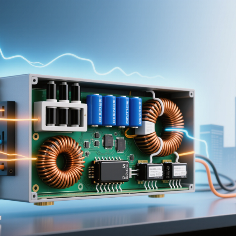
A switching power supply converts incoming AC power into regulated DC through rapid transistor switching. The EMI filter reduces electrical noise entering or leaving the unit. A rectifier then converts AC into pulsating DC, while a bulk capacitor smooths the voltage. In many designs, a power-factor-correction stage also shapes input current. The switching transistor chops the DC at high frequency, and a compact transformer transfers energy while providing electrical isolation. On the secondary side, rectifier diodes or synchronous switches convert the transformed waveform to DC. Output capacitors and inductors reduce ripple. A feedback circuit monitors output voltage and adjusts switching duty cycle when the load changes.
Component quality matters. A worn capacitor can increase ripple; poor thermal design can shorten transistor life. The European Commission Joint Research Centre’s Code of Conduct for External Power Supplies evaluates active efficiency at five load points: 10%, 25%, 50%, 75%, and 100%. This spread helps reveal performance beyond one ideal operating condition. Still, a datasheet cannot fully capture a hot, dusty enclosure.
Tips: Check ripple, isolation, and temperature ratings, not just rated wattage. Leave airflow around the supply. Measure output under the actual load; bench results may differ.
How an SMPS Converts and Regulates Power
An SMPS converts incoming power into a form a device can use, then actively keeps its output steady.
With an AC input, a rectifier first produces DC. A switching transistor rapidly turns that DC on and off, creating high-frequency pulses. The pulses pass through a transformer in isolated designs, where voltage can be changed and electrical separation provided. Other designs use an inductor instead. That is the core.
On the output side, diodes or synchronous switches rectify the pulses, while capacitors and inductors smooth them into usable DC. A feedback circuit samples the output voltage and adjusts the switching pulse width or frequency when conditions change. If a load suddenly draws more current, the controller responds to limit the voltage drop.
Output capacitors help, but they cannot correct every transient instantly. Heat still matters. Components, airflow, and operating temperature all affect reliability; a compact supply may run warm even when its output looks stable.
Engineers verify performance by measuring voltage ripple and response under changing loads, not just by checking the no-load voltage. One easy detail to overlook is that regulation has limits: excessive load or poor cooling can push the supply outside its rated range.
The Role of Feedback in Voltage Control
In a switched-mode power supply, feedback keeps the output near its intended voltage as the load changes. A resistor divider samples the output and sends a smaller signal to a controller. The controller compares it with an internal reference. A tiny difference matters.
If the output sags when a motor starts, the controller can adjust the switching duty cycle or frequency. This changes how much energy reaches the output. When the load falls, the controller reduces energy transfer. The response is fast, but not instant; a brief voltage dip may still appear on an oscilloscope.
In isolated supplies, feedback must cross an electrical isolation barrier, often through an optocoupler or another isolation method. The control loop also needs careful compensation to avoid oscillation. Poorly tuned feedback can cause the output to wander or respond too slowly. A schematic may make the loop look simple, yet real behavior depends on component tolerances, wiring, and electrical noise. Measuring the output under changing loads reveals more than checking its voltage at idle.
Common SMPS Types and Applications
Common SMPS designs are often grouped by how they convert voltage. A buck converter steps a DC voltage down, while a boost converter raises it. Buck-boost designs can do either, depending on input and load conditions. These non-isolated circuits appear in battery-powered equipment, vehicle electronics, and control boards. That distinction matters.
Flyback and forward converters use a transformer to transfer energy and can provide electrical isolation. Flyback designs are common in lower-power AC-to-DC adapters and small auxiliary supplies. Forward and related bridge topologies are often used at higher power, including industrial equipment and communications systems. The categories overlap in practice; a real supply may combine several conversion stages.
Applications shape the choice. A compact LED driver may need stable current and careful heat management. A computer supply must provide several regulated output rails as its workload changes. Battery chargers need suitable voltage and current control, while factory controls may require isolation and reliable operation amid electrical noise. Check the input range, output rating, temperature limits, and isolation requirements before choosing a unit. Small details matter. Efficiency figures alone can mislead, since cooling, load variation, and installation conditions also affect performance. Even a well-designed supply may run warmer than expected inside a sealed enclosure.
Typical SMPS Output Voltages in Common Applications
Switched-mode power supplies (SMPS) convert electrical power efficiently by switching at high frequency. Buck, boost, buck-boost, and flyback designs serve different voltage-conversion needs. These bars show representative DC output-voltage magnitudes: actual outputs vary by design and standard. Telecom systems commonly use a nominal −48 V supply; its magnitude is shown here.